Call
1-800-832-3647
Innovation by Design
Advanced Press Automation Products
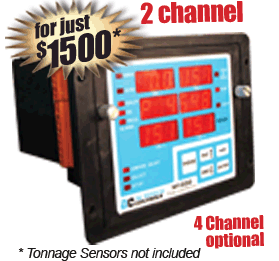
M1030 Series Tonnage Monitor
» Learn mode to automatically compute reference Tonnage!!
» Built-in sensor integrity check
» Programmable Tred limits
» Programmable Over & Under limits for Die, Process & Press-Protection
» Protection from Reverse/Snap thru Tonnage
» 2 Counters, 10 Programs
M1030 Series Tonnage Monitor
» Order your Short Form Catalog Affordable Die Protection, PLS, Brake, Shut-Height & Tonnage Monitor
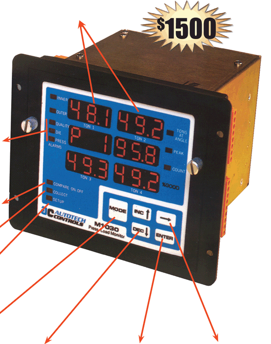
2 Sensors (expandable to 4) in one small panel Mount 7.25”x5.5”x5.9” Windows to Display Tonnage
Windows Display Tonnage values in Ton1, Ton2, Ton3, Ton4
Tonnage Sensors with
4-20 mA Output
Built-in Sensor Integrity Check detects Broken Sensor Wires
Alarms for Quality, Die, Press Normally “OFF”, “ON” if fault conditions occurs
Compare ON/OFF Mode Displays “ON”, comparison of reference profile as active
Collect Mode
Displays “ON” indicates “Collect Mode”
Setup Mode
Displays “ON” indicates “Setup Mode”
Mode Key This key is used to switch from one programming/viewing mode to the other
INC and DEC Keys These keys are used to increment/decrement numerical values Enter Key
Enter value into memory or to activate start for learn or reset for counter
Key
Switch between sub modes or options
Cost Effective Tonnage Monitor to Protect Press and Dies from Over & Under Tonnage

Programmable Load Monitor, Mini PLM M1030-E from Autotech, is one of the best investments in tools for a press. It offers an economical entry into the Press Load Monitoring.

The Low Cost M1030-E measures Load or Tonnage on a press by using strain gages mounted on load bearing members, such as press columns. The M1030-E compares the measured load against user programmed limits for Press Protection, Die Protection and for Process Trend.

If the measured load is outside the programmed limits, Mini PLM de-energizes the appropriate fail-safe relay that can be used to stop the press, warn the operator and/or signal supervisor control.

The Mini PLM uses strain gauge sensor with built-in amplifier for tonnage measurement. The sensors provide current signals proportional to tonnage. This makes wiring of sensors very easy. The user does not have to worry about length of wires or splitting of wires.
The Mini PLM has two counters for counting total number of hits, as well as the number of good pairs made. A part is considered good if it did not cause any alarm or fault during stamping.

Positive Tonnage Press Limit Negative Tonnage Press Limit
This limit is programmed by the user in Tons. The unit de-energizes “Positive Press Limit” relay when measured tonnage exceeds the limit. This limit is set around the rated tonnage of the press and intended to protect the press from overload. This limit comparison cannot be disabled. This limit is programmed by the user in Tons. The unit de-energizes “Negative Press Limit” relay when measured tonnage exceeds the limit. This limit is intended to protect the press from reverse or snap-through tonnage. This limit comparison can be disabled.
Die Protection Band Process Trend Band or Limits

The Die Protection Band is created by programming limits around a “reference” tonnage. The reference tonnage is automatically learned by the Mini PLM during unit setup. This unit measures the maximum tonnage in each press cycle and averages over a programmed number and hits.

The average tonnage is considered as reference. The Mini PLM maintains a reference for each installed sensor. User programs positive and negative deviation around this reference to create a die protection band.

The process Trend Band functions similar to Die Protect band, EXCEPT that the reference tonnage for process trend band, called Process Trend band, is not fixed at the time of setup.
Modes Key Pad
On the M1030-E, each display is considered to be a different mode. The detailed descriptions of the modes, displays, key responses are described in the Display Modes Reference. This list in the overview section refers to modes described in the reference section. The M1030-E has five simple keys for programming as well as operation of the unit. Response to key strokes in different modes is described in the Display Modes Reference.
Home | About Us | Order Catalog | Support | Downloads

Copyright © 2014 Autotech Controls. All rights reserved. All Product names, trademarks and registered trademarks are the property of their respective manufacturers or legal holders. Autotech Controls disclaims any proprietary interest in the marks or names of others. All prices are US List prices and are subject to change without notice.