

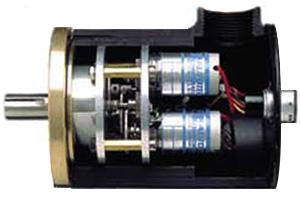
 Size 40 Dual (Multi-turn) DigiSolver
3. Multi-Turn:
18-bit Binary over 64 turns; 15-bit BCD or Standard Gray over 32 turns; Size 40 (E5N series) or explosionproof housing (E8N series). Internal gear train ratios of 64:1 or 32:1.
Single- or Multi-Turn Operation
The DigiSolver is an absolute encoder; that is, it keeps track of the exact shaft position even during power outage or switching-off the machine. At power-up, the DigiSolver's output will indicate the exact shaft position, even if the machine moved during the power outage.
In a single-turn operation, the machine cycle is completed during one complete revolution of the transducer shaft, whereas in a multi-turn operation the transducer shaft needs to make more than one turn for a complete machine cycle.
Example Part Numbers and Descripts are listed below:
| E5N-G5,10-8POME | Dual Multi-turn DigiSolver with military connector, NEMA 13, size 40 (4" dia), Heavy Duty, Gray code Output (32 total turns), Input 8-30 VDC,PNP Sourcing Transistor Digital Output |
| E5N-D5,10-8PPME | Dual Multi-turn DigiSolver with military connector, NEMA 13, size 40 (4" dia), Heavy Duty, BCD Output (32 total turns), Input 8-30 VDC,PNP Sourcing Transistor Digital Output with PC-sync circuit |
Specifications
ELECTRICAL |
Logic TRUE: Transistor ON, 1.7 V drop @ 100 Ma |
| E5N | E7N | E8N | Network Resolvers |
|
| Maximum Starting Torque @ 25° C (oz.-in): |
8.0 | 5.0 | 8.0 | E5, E7, and E8 Model Dependent |
| Moment of Inertia (gm/cm2) |
45 | 45 | 454 | E5, E7, and E8 Model Dependent |
| Shaft Sizes: | 5/8" | 3/8" | 5/8" | E5, E7, and E8 Model Dependent |
| Maximum Shaft Load Axial (lbs): Radial (lbs): |
50 100 |
40 36 |
50 100 |
E5, E7, and E8 Model Dependent |
| Bearing Life at Max. Mfr. Spec. (Rev.): |
2 x 10 | 2. x 10 | 2 x 10 | E5, E7, and E8 Model Dependent |
| Weight (lb.) | 4.5 | 2 | 6.5 | E5, E7, and E8 Model Dependent |
| Shock: | 200 g for 11 ms | |||
| Vibration: | 20 g to 2000 Hz | |||
| Operating Temperature (Ambient): |
-10° C to 85° C | -10° C to 85° C | -10° C to 85° C | -10° C to 70° C |
| Storage Temperature | -85° C to 302° C | |||
| Enclosure: | NEMA 13 | NEMA 13 | NEMA 4X Div. 1, Class 1, Groups B, C, and D |
Depends on Model |