Input Power:
105 to 135 VAC, 50/60 Hz, 30 W Operating
Temperature:
-10°F to 122°F (-23°C to 50°C)
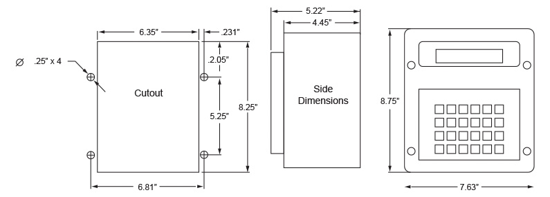
Dimensions:
7.6” W x 8.7” H x 5-1/4” D
RESOLVER INTERFACE
Position Transducer:
Resolver, Autotech’s Series E7R and RL100
Cable Length between Resolver and M1200:
2500 feet max, toil shielded,
Resolver Cable:
Autotech’s CBL-10T22-Mxxx
PROGRAMMING
Scale Factor:
Fixed at 360
Offset:
Programmable from 0 to 359; common to all
Die Protection and PLS programs
Die/Tool Identification:
One 8-character name per program.
Search by name.
Number of Programs or Setups:
60 programs
DIE PROTECT SPECIFICATIONS
Number of Sensors:
4, Expandable to 12
Event Detection:
Programmable rising edge, falling edge,
pulse, pos hi or pos low detection within
programmed window.
Die Protection Fault Output:
Programmable for each sensor:
E-STOP: Stops the press immediately (See
Engagement Angle).
T-STOP:
Stops the press at top.
Sensors can selectively be disabled.
Sensor Name:
One 8-character name per sensor. Ability to
select names from a library or enter a
customized name.
Slug Detect Delay:
Programmable number of stroke delays
between the detection of a slug fault and
the deactivation of the E-Stop or T-Stop
output.
E-Stop Engagement Angle:
Programmable angle from 90° to 190°.
E-Stop does not occur between Engagement
Angle and 190°.
Top-Stop Angle:
Programmable angle at which the Top Stop
output is activated, when required.
COUNTERS
Batch Counter:
Six digit presettable down counter. Counts
down to zero. Top Stop output de-energizes
at programmable T-Stop Angle, Resettable
from keypad or input.
Quality Counter:
Six digit presettable down counter. Counter
output de-energizes at programmable
T-Stop Angle when Quality Counter = 0
|
 |
Total Counter:
Six digit resettable up counter. Resets at
power up or from keypad or input.
Tool Counter:
Six digit tool specific up counter. Resets
from keypad.
INPUTS
Electrical Specifications (all inputs)
Optical isolation:
1500 V
Logic Levels (except 120V Brake Input):
TRUE: <1.0 VDC @ 7ma (or terminal
tied to Sig Ref. (J9-1)
FALSE: 20 to 24 VDC (or open circuit)
Fault Reset:
TRUE: Resets all faults including Die
Protection, Brake Wear, and Motion
Program and Supervisor Enable:
TRUE: Allows programming of parameters.
FALSE: Parameters can only be viewed.
Output Enable:
TRUE: allows all outputs to function
FALSE: De-energizes all outputs
Batch, Quality, and Total Reset:
Three separate inputs, one for each
TRUE: Resets the desired counter to
its preset value
FALSE: No action
OUTPUTS
Fault Output:
Detects resolver broken wire and M1200
internal faults. Without Fault: Relay
remains energized.
With Fault:
Relay de-energized.
Motion Output:
Relay energized when resolver RPM is
between programmed high and low motion
limits.
E-STOP Output:
Relay de-energized when Die Protection
Fault is detected. When no fault detected,
relay stays energized.
T-STOP Output:
Relay de-energized when Die Protection
Fault is detected. When no fault detected,
relay stays energized.
Counter Out:
Relay de-energized when Quality Counter
equals zero. Relay energized when counter
is non-zero.
TYPES OF OUTPUTS
A. Electromechanical SPST Relay:
10 Amp resistive continuous @120VAC
PLS SPECIFICATIONS
Number of PLS Outputs:
4, Expandable to 14
PLS Setpoints:
17 per program
Speed Compensation:
(Available for Channels 1-6 only):
Programmable up to 359 degrees per 100
rpm. Each PLS channel has its own speed
compensation.
|