
RD180 Remote Display Specifications
Input Power |
Programmable Scale Factor: 19 to 999 |
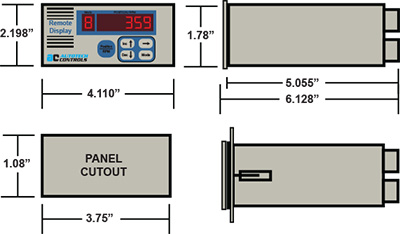 Mounting Dimensions
The figures to the right give mounting dimensions of the RD180 Remote Display. The unit is housed in a 1/8 DIN panel mount case and requires a rectangular panel cutout only (no mounting screw holes are required). Slide the unit in through the panel opening with gasket, insert the two right-angle mounting brackets into the openings on either side of the RD180 Remote Display housing and slide the brackets ¼” toward the back of the unit to secure the brackets to the housing. Tighten the pair of screws on the right-angle brackets to hold the unit into the panel. IMPORTANT: DO NOT OVER-TIGHTEN (80 inch-oz. torque max)!
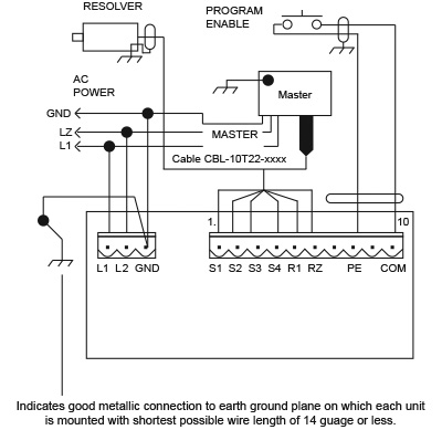 Rear View and Wiring Diagram
Notes on grounding and shielding (Failure to observe any of these requirements may cause unpredictable operation and will void warranty):
- All logic level wiring (including resolver and external power supply) must be done using overall fil shielded cables, with shields and equipment grounded as per above drawing. See How to Order section for suitable cables offered by Autotech.
- Resolver shielded cable must consist of twisted apirs, and the twisted pairs must be wired as per wiring instructions. See How to Order section for a suitable resolver cable offered by Autotech.
- All ground planes on which the RD180 Remote Display and all external equipment are mounted must be held to the same RF potential, by good metallic connections to building grames, conduit or wiring trays.
- All shielded cable must be kept at a minimum distance of 2 inches from all high voltage or inductive wiring.
- All shielded cable must be kept at a minimum distance of 12 inches from all motor wiring controlled by AC or DC drives.